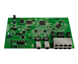
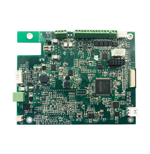
Through Hole Soldering Circuit Board Turnkey electric Pcb
Name: Through Hole Soldering Circuit Board Turnkey electric Pcb
Origin: China
Certified: UL, CE, RoHS
Copper Thickness: 3 oz
Base Material: FR4/ROGERS/Aluminum/High TG
Board Thickness: 0.2mm-7.0mm
Application: Electronics Device
Surface Finishing: HASL\OSP\immersion Gold
Solder mask color: Blue. green. red. black. white. etc.
What is a circuit board with through-hole soldering?
- Traditional methods for assembling and soldering electronic components on circuit boards include through Hole Soldering Circuit Board. In this method, the circuit board’s holes are drilled and the component leads or legs are put into the holes. After that, the leads are soldered to the board’s opposite side to create a mechanical and electrical connection.
- Compared to other assembly techniques, through-hole soldering has a number of benefits, especially in terms of dependability and mechanical strength. This approach produces solder joints that are typically more durable and resilient to mechanical stress and vibrations, making them ideal for situations where longevity is crucial. Better heat dissipation capabilities are also provided, which are essential for high-power applications.
What You Need to Know About Through-Hole Soldering for Circuit Boards?
Connecting electrical components to circuit boards is a process called Through Hole Soldering Circuit Board. To establish a safe and conductive connection, component leads must be inserted through board holes and soldered. An explanation of through-hole soldering for circuit boards is provided below in step-by-step way:
-
Gather the necessary tools and materials:
a soldering iron with a suitable tip, solder wire (preferably lead-free), flux (optional but recommended), solder wick or a desoldering pump (for removing solder), a sponge or wet sponge for cleaning the soldering iron tip, and safety gear like safety glasses and heat-resistant gloves.
-
Make the circuit board ready:
Make sure that the circuit board is dust- and debris-free. If necessary, clean the board’s surface with a brush or compressed air.
-
Identify the parts:
Make a list of the parts you must solder onto the board and make sure they are close at hand.
-
Component insertion:
Place the components in the circuit board’s corresponding holes by inserting their leads. Make sure the leads are positioned correctly and fit firmly into the openings.
-
Secure the components:
Securing the elements Keep the parts in place when you turn the circuit board over. The components will stay in place if the board contains pre-tinned pads, which are covered with a thin coating of solder.
-
Soldering iron heating:
Switch on the soldering iron and let it become warm. Typically, a temperature range of 300 to 350 degrees Celsius (570 to 660 degrees Fahrenheit) is the best for through-hole soldering. Consult the instructions for your soldering iron from the manufacturer.
The process of Through Hole Soldering Circuit Board:
- Through-hole soldering is a multi-step procedure. The leads of the components are first placed into the holes on the circuit board that correspond to them. The leads are then soldered using a soldering iron or wave soldering machine while the board is then turned around. Trimming extra solder is done, and the alignment and quality of the junction are checked.
- Although through-hole soldering has been commonly used for a long time, recent years have seen a decline in its utilization as surface mount technology (SMT) has grown more popular. Higher component density, more compact form factors, and automated assembly procedures are all features of SMT. However, there are still some cases when through-hole soldering is appropriate, such as with big and heavy components, high-power electronics, and where rework or repair may be required.


