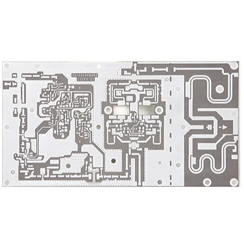
Name: TACONIC High Frequency PCB
Material: TACONIC
Layers: 2L
Copper Thickness: 1oz
Plate thickness: 0.8MM
Minimum line width: 0.7MM
Special process: high frequency board, Teflon material
Minimum line spacing: 0.25MM
Surface Treatment: Immersion Tin
ISOLA 370HR High Frequency PCB
Name: ISOLA 370HR PCB
Material: isola 370hr HIGH TG PCB
Df (dissipation factor): 0.021
Dk (dielectric constant): 4.04
Glass transition temperature: TG180℃
Td: 340℃
Number of Layers: 6 layers
Board thickness: 1.0mm
Surface technology: Immersion gold
Copper thickness: 1OZ
Minimum line width/line spacing: 4mil/4mil
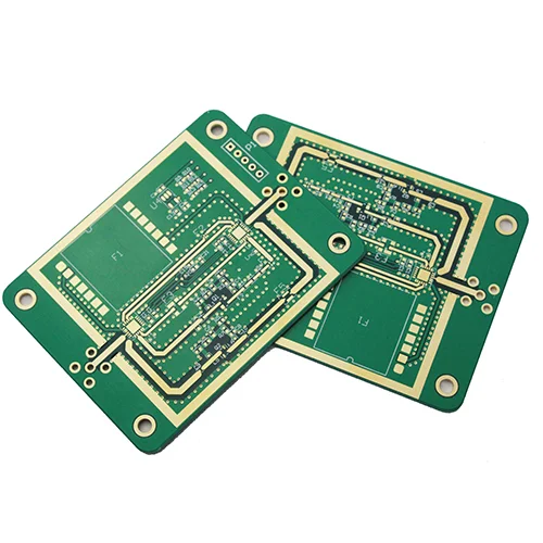
Rogers RO4350B Radio Frequency PCB (RFPCB)
Name: Rogers RO4350B RF PCB (RFPCB)
DK: 3.48+/-0.05
Layers: 4 layers
Dielectric thickness: 0.254mm (20mil)
Finished thickness: 0.8mm
Material Copper Thickness: ½(17μm)
Finished copper thickness: 1OZ (35μm)
Surface Treatment: Immersion Gold
Application: Instrument PCB, RF PCB, Radar Instrument PCB
Rogers RO4350B High Frequency Board
Name: Rogers RO4350B High Frequency Board
Layers: 4L
Sheet: Rogers RO4350B
Plate thickness: 1.6MM
Dielectric Constant: 3.48
Copper thickness: base copper 0.5OZ, finished copper thickness 1OZ
Surface Treatment: Immersion Gold
Uses: RF communication instruments, microwave antenna circuit boards
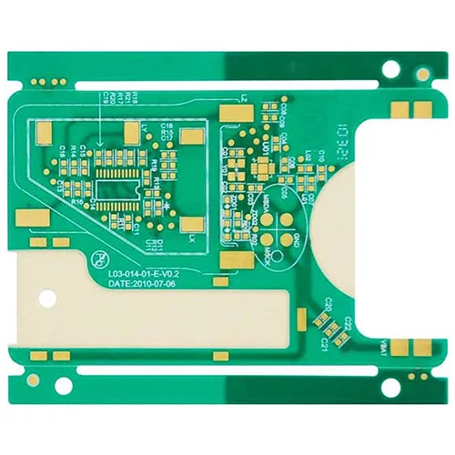
Name: Rogers RO4350B PCB
D K: 3.48+/-0.05
Layer: 2L
Dielectrics Thickness: 0.762mm (30mil)
Finished Thickness: 0.85mm
Material Copper Thickness: ½(17μm)HH/HH
Finished Copper Thickness: 1OZ (35μm)
SurfaceTreatment: Immersion Gold
Application: Instrument PCB, Radio Frequency PCB, Radar Gauges PCB
Rogers RO4350B High Frequency Board
Name: Rogers RO4350B High Frequency Board
Material: Rogers RO4350B
Layer: 2L
DK: 3.48
Dielectric Thickness: 0.762mm
Thermal Conductivity: 0.69w/m.k
Flammability: 94V-0
Volume Resistivity: 1.2*1010
Surface Resistivity: 5.7*109
Finished Thickness: 0.8MM
Copper Thickness: Base 0.5OZ, Finished 1OZ
- PCB Capability
- PCB manufacturing equipment
- PCB Materials
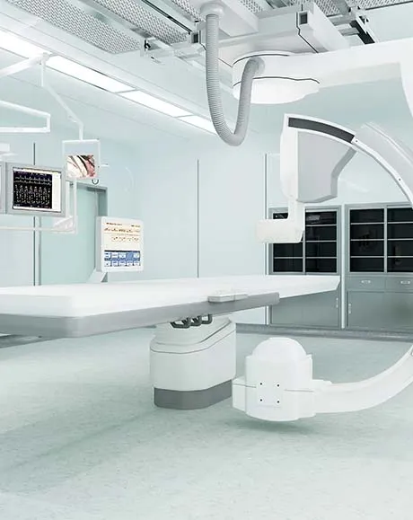
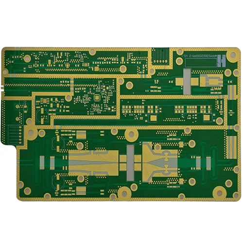
Introducing our high Frequency PCB , the pinnacle of excellence in the realm of RF and microwave applications. Designed to meet the demanding requirements of high-frequency signals, our high-frequency PCBs offer exceptional performance, reliability, and signal integrity.
Our high-frequency PCBs are meticulously engineered using specialized materials and advanced manufacturing techniques. These PCBs are specifically tailored to operate in the microwave and RF frequency range.
Moreover, this makes them ideal for applications such as wireless communications, satellite systems, radar systems, and high-speed data transmission.
Advantages of High-Frequency PCB:
- Excellent Signal Integrity: High-frequency PCBs are designed to maintain signal integrity and minimize signal loss at high frequencies. These PCBs utilize low-loss materials with controlled dielectric constants. Moreover, it ensures a superior impedance control, reduced insertion loss, and improved return loss.
- Wide Frequency Range: Our high-frequency PCBs are capable of operating in a wide frequency range, from a few megahertz (MHz) to several gigahertz (GHz). This versatility makes them suitable for a variety of applications, including wireless communication systems, microwave devices, and high-speed digital circuits.
- Low Transmission Loss: High-frequency PCBs are built using materials with low dissipation factors and low dielectric losses. This results in minimal transmission loss, allowing for efficient signal transmission and reception, especially in high-speed and high-frequency applications.
- Impedance Control: Maintaining impedance control is crucial for high-frequency signals. Our high-frequency PCBs are engineered to provide precise impedance matching, ensuring maximum power transfer and minimizing signal reflections. This also leads to improved system performance and reduced signal distortions.
- High Thermal Stability: High-frequency PCBs are designed to withstand the challenges of thermal management in high-power applications. They employ thermally conductive materials and efficient heat dissipation techniques. It also ensures stable performance even under elevated temperature conditions.
| Item | Capability |
| Layer Count | 1-40layers |
| Base Material | KB、Shengyi、ShengyiSF305、FR408、FR408HR、IS410、FR406、GETEK、370HR、IT180A、Rogers4350B、Rogers4000、PTFE Laminates(Rogers series、Taconic series、Arlon series、Nelco series)、Rogers/Taconic/Arlon/Nelco laminate with FR-4 material(including partial Ro4350B hybrid laminating with FR-4) |
| Board Type | Backplane、HDI、High multi-layer 、blind&buried PCB、Embedded Capacitance、Embedded resistance board 、Heavy copper power PCB、Backdrill. |
| Board Thickness | 0.2-5.0mm |
| Copper Thickness | Min. 1/2 OZ, Max. 10 OZ |
| PTH Wall | 25um(1mil) |
| Maximum Board Size | 1100*500mm(43”*19”) |
| Min laser drilling size | 4mil |
| Min. Spacing/Tracing | 2.7mil/2.7mil |
| Solder Mask | Green, Black, Blue, Red, White, Yellow, Purple matte/glossy |
| Surface Treatment | Flash gold(electroplated gold)、ENIG、Hard gold、Flash gold、HASL Lead-free 、OSP、ENEPIG、Soft gold、Immersion silver、Immersion Tin、ENIG+OSP, ENIG+Gold finger, Flash gold(electroplated gold)+Gold finger, Immersion silver+Gold finger, Immersion Tin+Gold finger. |
| Min. Annular Ring | 3mil |
| Aspect ratio | 10:1(HASL Lead-free 、HASL Lead、ENIG、Immersion Tin、Immersion silver、ENEPIG);8:1(OSP) |
| Impedance control | ±5ohm(<50ohm), ±10%(≥50ohm) |
| Other Techniques | Blind/Buried Via |
| Gold Fingers | |
| Press Fit | |
| Via in Pad | |
| Electrical Test |

PCB Drilling machine

PCB pattern plating line

PCB solder mask expose machine

PCB pattern expose machine

Strip film etching line

Solder mask screen silk print machine

Solder mask scrubbing line

PCB Flying Probe Test (FPT)

Fully automatic exposure machine
| Here there’re many laminate material datasheets, they’re useful and helpful for you, please see them: | ||||||||
| SUPPLIER | PCB LAMINATE | TYPE | MATERIAL DATASHEET | TG | TD | DK(1MHZ) | DK(1GHZ) | DK(10GHZ) |
| KB | KB-6160 | FR4 | DOWNLOAD | 135 | 305 | 4.35 | – | – |
| KB-6160A | FR4 | DOWNLOAD | 135 | 305 | 4.35 | – | – | |
| KB-6160C | FR4 | DOWNLOAD | 135 | 314 | 4.7 | – | – | |
| KB-6150 | FR4 | DOWNLOAD | 132 | 305 | 4.6 | – | – | |
| KB-6150C | ||||||||
| KB-6164 | FR4 | DOWNLOAD | 142 | 330 | 4.8 | – | – | |
| KB-6164F | FR4 | DOWNLOAD | 145 | 340 | 4.8 | – | – | |
| KB-6165F | FR4 | DOWNLOAD | 150 | 346 | 4.8 | – | – | |
| KB-6167F | FR4 | DOWNLOAD | 170 | 349 | 4.8 | – | – | |
| SHENGYI | S1141 | FR4 | DOWNLOAD | 135 | 310 | 4.6 | – | – |
| S1141KF | FR4 | DOWNLOAD | 140 | 350 | 4.7 | – | – | |
| S1000 | FR4 | DOWNLOAD | 155 | 335 | 4.9 | – | – | |
| S1170 | FR4 | DOWNLOAD | 170 | 335 | 4.6 | – | – | |
| S1000-2 | FR4 | DOWNLOAD | 170 | 335 | 4.8 | – | – | |
| S1155 | FR4 | DOWNLOAD | 135 | 370 | 4.7 | – | – | |
| ITEQ | IT-158 | FR4 | DOWNLOAD | 150 | 340 | 4.6-4.8 | – | – |
| IT-180 | FR4 | DOWNLOAD | 180 | 350 | 4.5-4.7 | – | – | |
| TUC | TU-768 | FR4 | DOWNLOAD | 180 | 350 | – | 4.3-4.4 | 4.3 |
| TU-872 | Modified Epoxy | DOWNLOAD | 200 | 340 | – | 3.8-4.0 | 3.8 | |
| ROGERS | RO 3003 | Cer/PTFE | DOWNLOAD | – | 500 | – | – | 3 |
| RO 3010 | Cer/PTFE | DOWNLOAD | – | 500 | – | – | 10.2 | |
| RO 4003 | Hydrocarbon/Cer | DOWNLOAD | >280 | 425 | – | – | 3.38 | |
| RO 4350B | Hydrocarbon/Cer | DOWNLOAD | >280 | 390 | – | – | 3.48 | |
| RT/duroid 5880 | PTFE/Glass | DOWNLOAD | – | 500 | – | – | 2.2 | |
| ISOLA | Polyclad 370HR | FR4 | DOWNLOAD | 170 | 340 | 4.8-5.1 | – | – |
| FR406-HR | FR4 | DOWNLOAD | 190 | 325 | 3.91 | 3.86 | 3.81 | |
| FR408-HR | FR4 | DOWNLOAD | 200 | 360 | 3.72 | 3.69 | 3.65 | |
| P96 | Polyimide | DOWNLOAD | 260 | 416 | – | 3.78 | 3.73 | |
| Hitachi | MCL-BE- 67G | Modified Epoxy | DOWNLOAD | 140 | 340 | 4.9 | 4.4 | – |
| MCL-E-679F | FR4 | DOWNLOAD | 170 | 350 | 4.2-4.4 | 4.3-4.5 | – | |
| MCL-LX-67Y | Special Laminate | DOWNLOAD | 185-195 | 325-345 | – | 3.4-3.6 | – | |
| Nelco | N4000-13 | Modified Epoxy | DOWNLOAD | 210-240 | 365 | – | 3.7 | 3.6 |
| N4000-13EP | Modified Epoxy | DOWNLOAD | 210-240 | 350 | – | 3.4 | 3.2 | |
| N4000-13SI | Modified Epoxy | DOWNLOAD | 210-240 | 350 | – | 3.4 | 3.2 | |
| N4000-13EP SI | Modified Epoxy | DOWNLOAD | 210-240 | 350 | – | 3.4 | 3.2 | |
| Taconic | TLX-6 | PTFE | DOWNLOAD | – | – | – | – | 2.65 |
| TLX-7 | PTFE | DOWNLOAD | – | – | – | – | 2.6 | |
| TLX-8 | PTFE | DOWNLOAD | – | – | – | – | 2.55 | |
| TLX-9 | PTFE | DOWNLOAD | – | – | – | – | 2.45 | |
| RF35 | PTFE | DOWNLOAD | <315 | – | 3.5 | – | 3.5 | |
| TLC-27 | PTFE | DOWNLOAD | – | – | – | – | 2.75 | |
| TLC-30 | PTFE | DOWNLOAD | – | – | – | – | 3 | |
| TLC-32 | PTFE | DOWNLOAD | – | – | – | – | 3.2 | |
| Arlon | Arlon 25N | Cer | DOWNLOAD | 260 | – | – | – | 3.38 |
| Arlon 25FR | Cer | DOWNLOAD | 260 | – | – | – | 3.58 | |
| Arlon 33N | Polymide | DOWNLOAD | >250 | 353 | 4 | – | – | |
| Arlon 35N | Polymide | DOWNLOAD | >250 | 363 | 4.2 | – | – | |
| Arlon 85N | Polymide | DOWNLOAD | 250 | 387 | 4.2 | – | – | |
| Stablcor | ST325 | – | DOWNLOAD | Thermal conductivity:75w/m.k(with 1oz copper) | ||||
| ST10 | – | DOWNLOAD | Thermal conductivity:325w/m.k(with 1oz copper) | |||||
| Panasonic | R-1566W | FR4 | DOWNLOAD | 140 | 330 | 4.95 | 4.7 | 4.65 |
| Ventec | VT-901 | Polymide | DOWNLOAD | 250 | 390 | 4.2-4.5 | 4.0-4.3 | – |
| VT-90H | Polymide | DOWNLOAD | 250 | 390 | 4.2-4.5 | 4.0-4.3 | – | |
| Bergquist | ht-04503 | – | DOWNLOAD | Thermal conductivity:2.2w/m.k(with 1oz copper) | ||||
Manufacture high frequency PCBs with small impedance tolerance and optimized RF performance; master core technologies to minimize expansion and contraction of RF microwave PCBs
Surface Finish - ROHS - Immersion Tin, Gold, Silver, Board Size - From 6mm*6mm to 475mm*475mm, Board Thickness - 0.4mm to 5mm, Min Track/Spacing - 3mil/3mil, Impedance Tolerance – 10%

we provide 24-hour service and support, you will receive a reply to your question within 2 hours and a quotation within 24 hours.

Before the official production of the PCB, we will conduct a free DFM review service and support free Allegro, Altium, Protel, PADS, OBD, Gerber and other formats.
We support TACONIC PCB business, Leadsintec is a professional one-stop PCBA service factory, Welcome t...
Leadsintec provides ISOLA 370HR PCB services. This is a PCBA one-stop assembly factory with senior ind...
We are a professional PCBA one-stop assembly factory, Leadsintec supports Rogers RO4350B RF PCB (RFPCB...
We support Rogers RO4350B High Frequency Board business, Leadsintec is a professional one-stop PCBA ser...
Leadsintec supports Rogers RO4350B PCB business, we are a professional PCBA one-stop assembly factory,...
We provide Rogers RO4350B High Frequency Board services. Leadsintec is your one stop turnkey PCB assem...